|
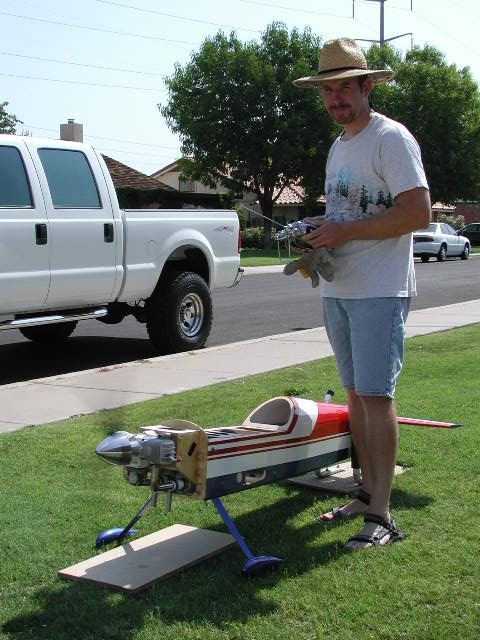
33% Cap Cowl, Engine and Canister Install
Below are the details of the
engine and canister muffler install in the 33% Cap 232, beginning with the
cans because I got them before the engine. The cans will be pretty easy, the KS94's are advertised as being especially
for Caps, they are shorter than most. I bought them from
Amelung Modelbau. They
are spec'd for an 80cc cylinder
(ZDZ80), so 50cc's apiece from my DA100 will be no problem. There is
already an open bay on the bottom of the fuse that is perfect for an air
exit, and I will extend the bottom of F2 to make the real wall of the
tunnel. Fill in the bays on the side of the motorbox, build a clamp
to hold everything in place, put a lid on it, and there you have it.
Note - these are a mixture of
pics from plane 1 and plane 2. They are nearly identical, where
there were differences I've included shots from both.
33% Cap Main 33% Cap Canister Install
33%Cap Headers
33% Cap Flight Reports
|
|

History
Projects/Reviews
Carl Goldberg Falcon 56
MkII
Colombo Andersson 38% Extra
Hangar 9 33% Cap 232
Hangar 9 1.20 Cap 232
(Bob's)
Hangar 9 1.20 Cap 232
(Bill's)
Lanier 31.5%
Staudacher S600
Sig Kadet Mk II
Sterling Ringmaster
Thunder Tiger Fun
Tiger
Updated!!
Pics of Cool
Stuff
Crash
Pictures
Car Stuff
Updated!!
1989 Jaguar XJS
Updated!!
Random Thoughts
Links
Stuff for Sale
Contact
Bob
Bill
|
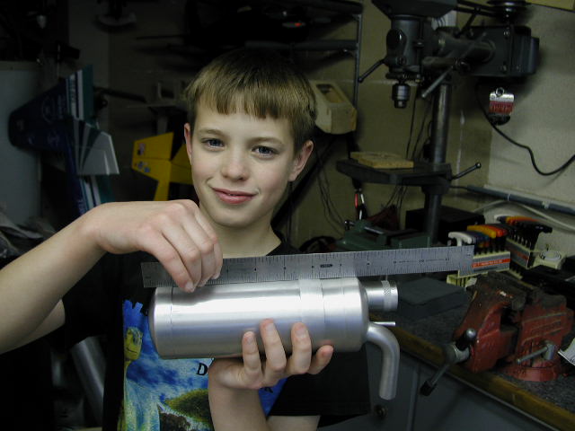
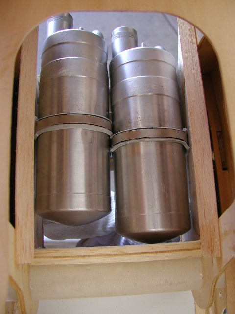
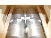
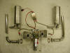
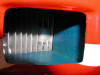
The KS-94Vs cans measure about 9"x3"
|
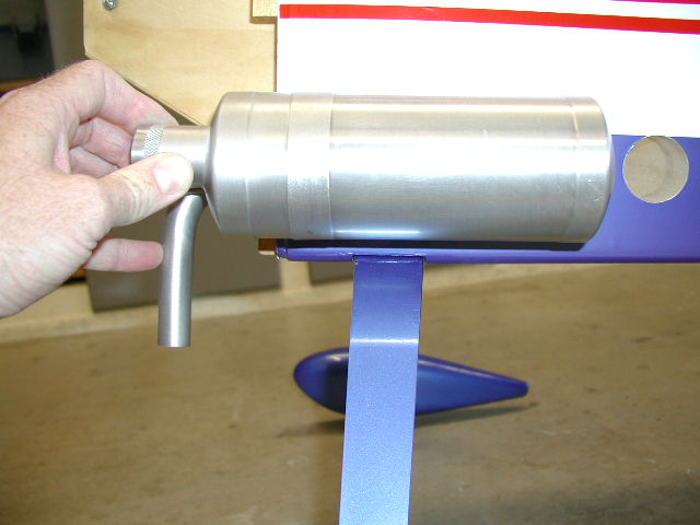
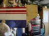
This is about how they'll sit in the
fuse |
They'll just fit between the sides of the motorbox
|
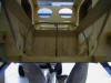
Front view before any cutting |
|
Approximate area to be removed
|

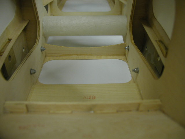
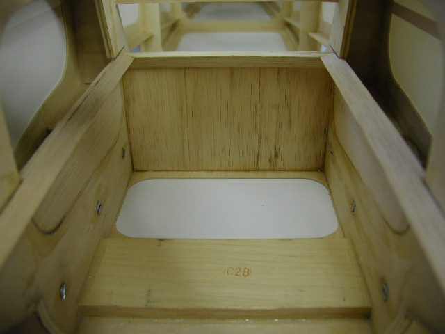
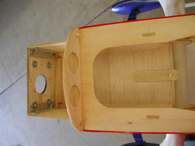
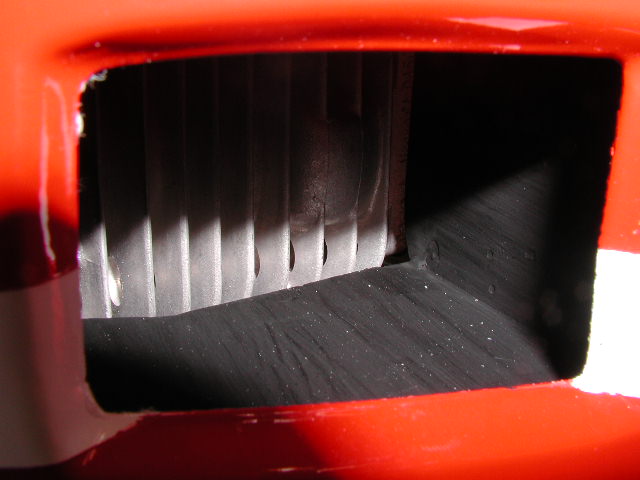
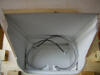
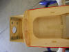
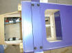
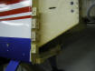
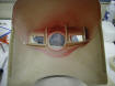
Inside of fuse "before", thru firewall. The bolts are part of the
landing gear structure and will need to be replaced with countersunk
flatheads. The white rectangle below the bolts is covering and will
be removed to create the air outlet.
|
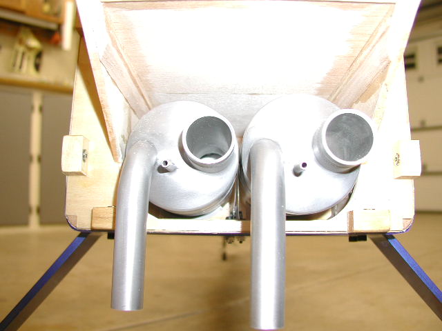
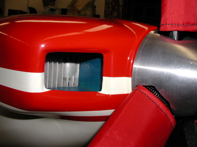
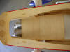
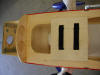
Front view right after cutting. White tube is for wing tube (spar). |
|
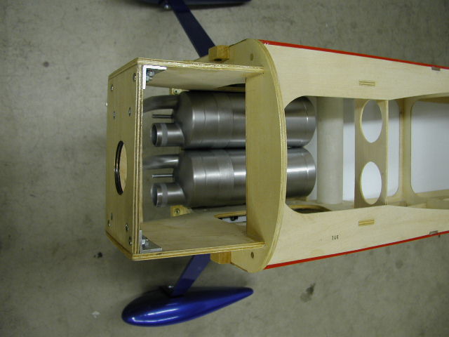
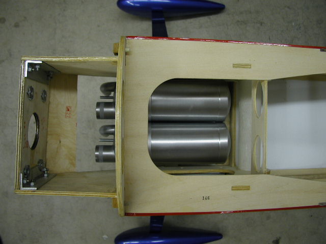
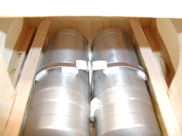
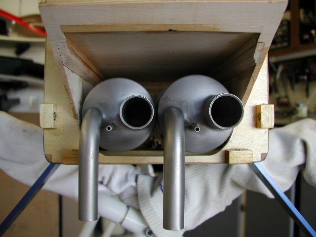
Three views: Cans laying in place after the front cut is made.
Notice that the can inlet and outlet are side by side rather than
vertical...not a big deal, the pipes will just be a bit off center.
|
|
 |
 |
|
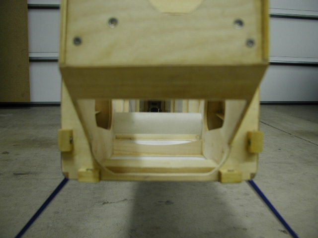
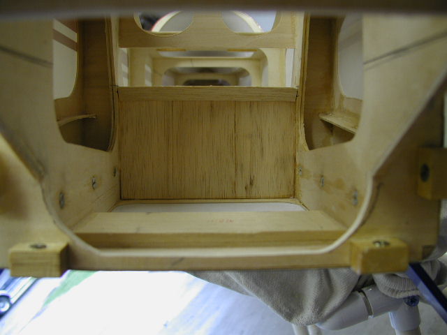
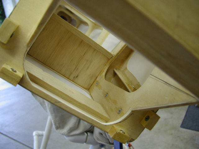
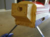
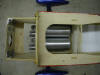
Two views: The rear wall of the
tunnel is in place and the 6 bolts have been replaced with countersunk
flatheads. The clamp will fasten to the landing gear plate, visible
at the bottom.
|
 |
 |
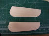
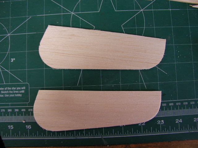
The 1/8 balsa pieces that will fill
in the bays in the sides of the motorbox
|
|
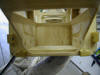
Two views: Side fillers are in,
and triangular stock has been run around the top edges. Once the
clamp is ready to go in, the top will be sheeted with 1/8" balsa.
|

|
|
|
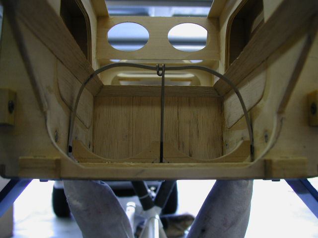
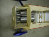
My first clamp design. The wire has 4-40 threads on the bottom, the
clamp is tightened via a locknut on the bottom of the plane, between the
main gear. The white pads are an Aerotrend tuned-pipe coupler that I
cut up. Problem was the clamp tended to pull the cans together and
the pads left dents in the cans. The walls of the cans are thin and
easy to dent.
|
 |
 |
|
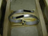
Final clamp design, similar to the clamps shown on
Edge540.com.
The strap is .032 aluminum, the pads are a Macs tuned-pipe coupler cut
into strips, glued to the cradle and strap with black RTV. Two #6x1"
bolts pass thru the bottom of the plane and the main gear, locknuts on the
bottom allow the clamps to be tightened. This design does a good job
of allowing the cans to pivot around a bit without touching each
other or the sides of the box. It took a bit of fiddling to get this
right, there just isn't much width to work with.
|
 |
 |
|
Another shot of the new clamp design.
I am still a bit concerned about heat, even though it seems I will have
plenty of airflow. I decided to coat the inside of the box with a
brush-on ceramic heat shield product from
BVM. It has the consistency
of watery drywall paste and goes on like house paint. The label says
it's impervious to fuel and chemicals. It will be interesting to see
how it holds up.
|
 |
 |
|
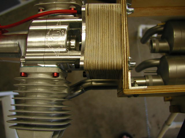
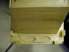
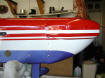
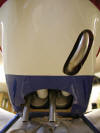
Bottom view shows the two locknuts used to tighten the clamps and the air
outlet. Extra hole is from the original clamp, need to fill it.
The cans and clamps are staggered so that the headers will be the same
length from each cylinder of the DA100. Staggering the clamps also
gave more room for the clamps so they don't interfere with each other.
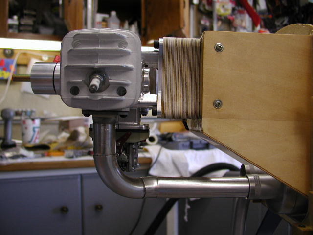
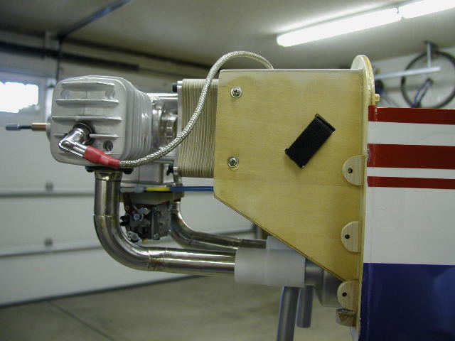
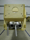
Side view shows the pipes. The headers will end up between 11"-13"
long, near as I can figure. I used Bill's BME 102 for a rough
guesstimate, as I don't have the DA yet..
|
 |
 |
|
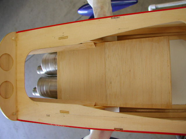
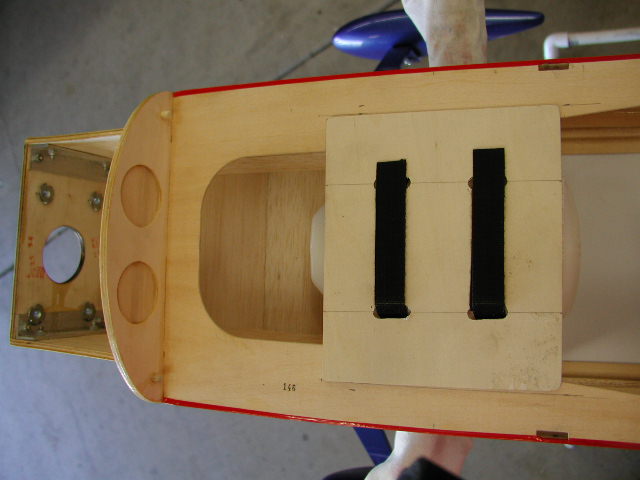
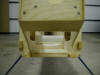
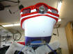
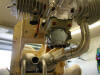
Near pics: I decided to make the top cover removable. It slides in
and out on a "track" formed by triangular stock. Top pic shows it halfway
closed, bottom pic shows it fully closed. Thin ply tab gives
something to grab on to slide it open, and a single screw secures the
cover. I don't anticipate having to open it much, but it
will make adjusting the clamps, scrubbing behind the ears, etc, much
easier. The cover is 1/8" balsa with a 1/4" square stock frame.
Note that the top part of F3 has been cut out.
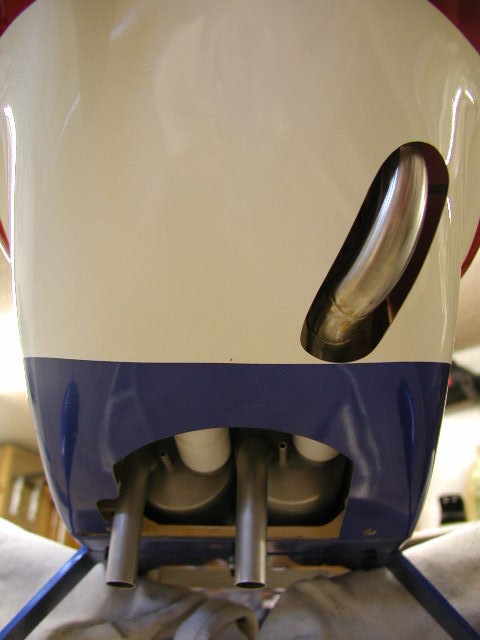
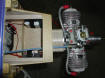
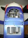
Far pics: Plane #2, from the bottom with the top cover removed, shows
ignition, ign battery, hot air exit. Did a better job saving the
covering on this one.
|
Plane #1
|
Plane #2
|
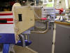
|
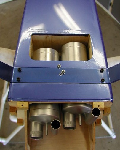
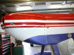
Tank mount, which replaces the top of F3. There is about 1" between
the bottom of the tank and the top cover of the muffler box. Front
view, there is about 3/4" between the top of the cans and the top
cover of the box. Should be plenty of room for good airflow.
|
 |
 |
|
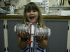
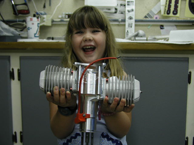
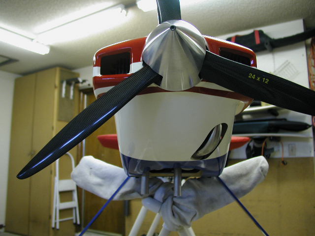
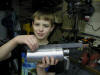
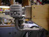
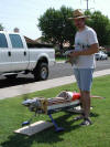
This is how excited I
am to finally receive my new DA100!
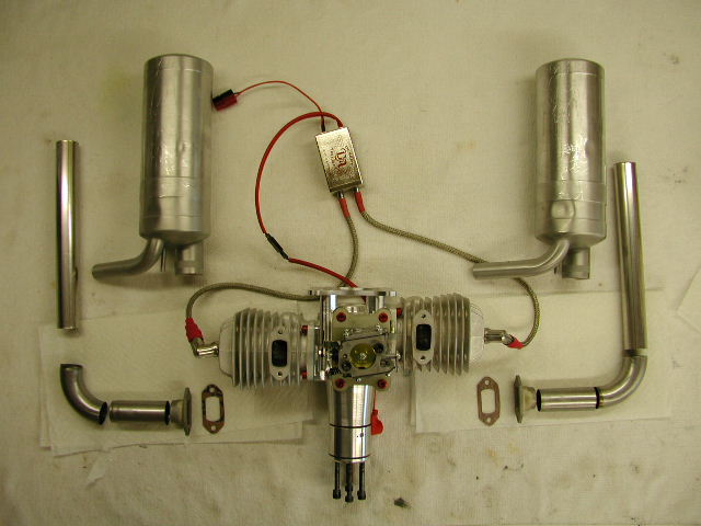
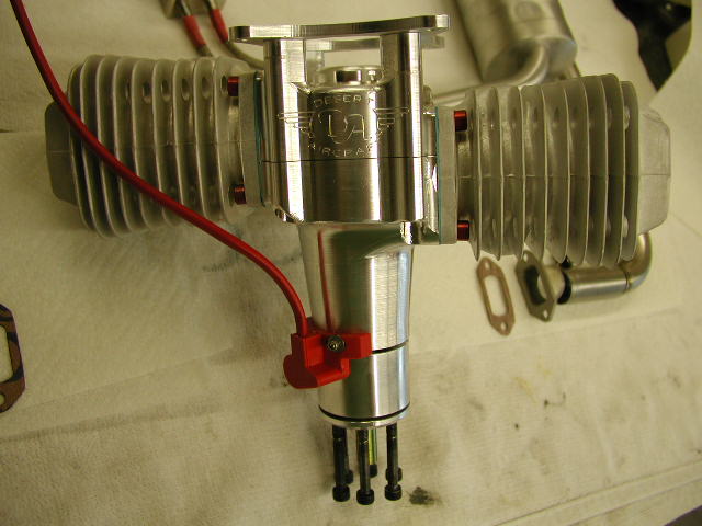
|
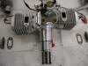
DA100 from the bottom. |
Another shot of the DA 100 with the
ignition and exhaust parts. |
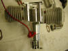
DA100 from the top. |
|
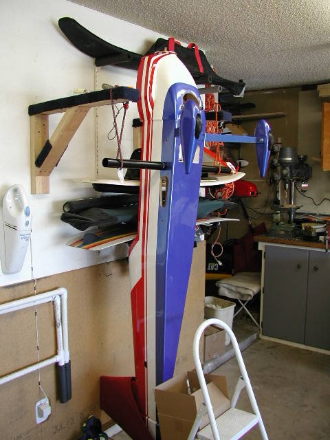
To get the motor lined up with the cowl on plane #1, I suspended the plane vertically,
sat the motor and spacer on the firewall, and put the cowl on. Next
I reached thru the (rough-cut) hot air exit and slid the motor around to
get it centered in the cowl, then marked the mount and the firewall.
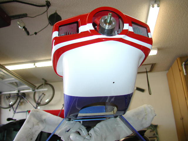
Since the cowl is not really adjustable on this plane, when the motor is
lined up with the cowl it should be centered up with the plane. The
cowl fit wasn't great, so I ended up doing some re-fitting of the cowl
first, then lining up the motor, and finally checking the centerlines of
the motor and fuse. Everything seems to be groovy. To get the
final cowl fit right, I ended up building a cowl ring. A lot of
work, and it required 5/16" holes in the side to enable me to reach thru
and tighten the bolts.
|
 |
 |
|
For
plane #2, I decided it made more sense to center the motor, then align the
cowl with the motor. The firewall was already drilled for a GT-80,
which has the mounting holes centered around the crank (true for most
engines, I believe..) I found the center of the firewall and then
lined up the DA100 mounting pattern around it. |
On plane #2, I ca'd strips of 1/16 ply to the inside of the cowl to strengthen the
mounting holes. This also helps get rid of the "flare" or bell shape
that the back edge of this cowl has. |
I added two extra mounting blocks on the sides, and pinned on all the
blocks with dowels. The original holes are the ones near the center
of the top and bottom blocks. |
|
The
cowl on plane #2 was a pretty bad fit out of the box. I had to take about 3/16" off
the back edge to get it squared up. It was overall too big. I
hate it when the cowl and hatch don't line up, so I pushed all the slack
down to the bottom, where it will be less noticeable. The down side
of this is that the stripes don't line up exactly.
|
Cowl is held in place with a total of 10
4-40's and #6 sealing washers from
McFeeley's.
(Thanks Joe Hunt for the McFeeley's tip!!) |
Yeah, yeah, it's overkill, but it won't move,
and I can run a nice tight spinner gap with no worries.
|
Small hole is for the choke wire.
|
|
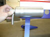
Three views of the first header, ready to be brazed up. It is about
11" long, which should be fine, according to DA. The header
pipe is 25mm and the inlet in the can is 30mm, so I have to figure out
some sort of teflon reducer...
|
 |
 |
 |
|
The headers all brazed up and ready
to run...I learned two keys to doing decent braze work: 1) Clean the
joints very thoroughly, (I used lacquer thinner) and 2) Only put flux where
you want braze to flow. Click
Here for details...
|
 |
 |
(This is plane #1, and you can see that the
cowl blocks have been moved inboard to accommodate the cowl ring.) |
|
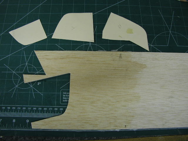
Building the cowl baffles on plane #2. Material is 1/8 balsa sheet
with a single layer of fiberglass cloth epoxied on one side. Most of
my summer flying is done in the late afternoon, when it can be 105 degrees
outside. I've never had overheating problems, but then again I've
never tried the plane without baffles. |
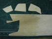
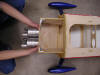
Patterns made from manila folder... |

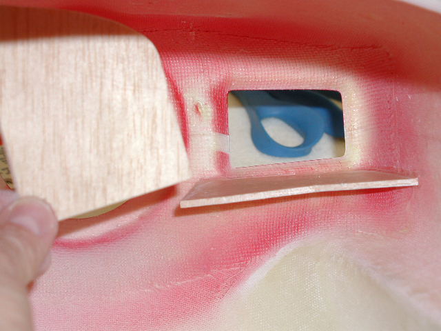
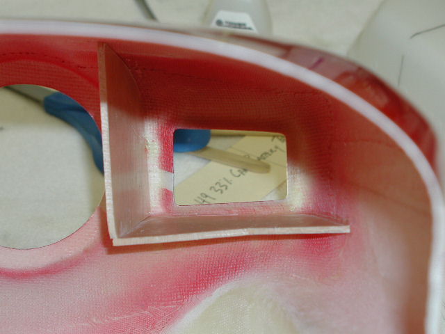
Bottom piece is glued in place, preparing to
test fit side piece. I used thick CA to glue everything in. Be
sure to de-grease mating surfaces. |

Side piece in place for a test fit. If
you use CA, you only get one shot to position, so the fit has to be right.
I use a pencil to make reference marks on the inside of the cowl, to help
line things up quickly.
|
|
All
baffles in place on plane #2. I don't think you need them on top, as
the cylinders are close to the cowl already. The purpose of the
baffles is to force air through the cooling fins, rather than letting
it all out the bottom. Also, they help keep the wind blast away from
the carb.
|

|

Completed baffles on plane #2. A bit
smoother but not perfect. Need to get some carbon fiber sheet to
make the next set out of... |

Completed baffles on plane #1. A bit
rough because I didn't press out the glass cloth while the epoxy was
curing.
|
|
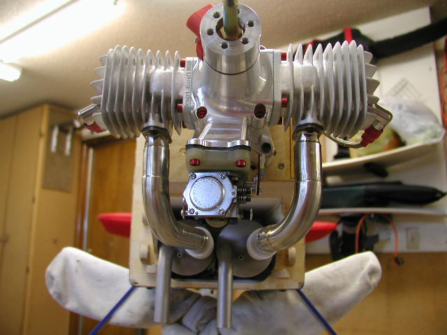
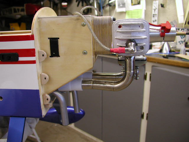
Headers with the cowl on. I
polished them with a "scotch pad" wheel on my grinder. I think the
pipe sticking thru looks kinda cool.. :-) |

|
 |
|
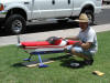
Fired up the motor today. Following the
directions exactly: Lawnboy Ashless 32:1, ignition on, choke it,
flip till it pops, open choke, flip till it starts. Never took more
than 5 flips to start, hot or cold. The air temperature was about
110 degrees, with the cowl off the hottest spot I could find was 165
degrees at the exhaust port, cowl on it was about 210 degrees. It
sounds really good, very mellow, I swear it isn't much louder than my
Saito 1.80. Need to get a db meter on it to know for sure.
97db at 3 meters over asphalt at full throttle!!
John and Gary from our local club (Arizona
Model Aviators) were kind enough to run an official sound check for me
on Saturday the 19th. I needed to be below 100db, made it with 3 to
spare. I'm pleased, I expected it to be closer.
|
|
|
 |
|
|
|
|